Monday 21 December 2015

Idler + torque tube assembly

Happy with my new idler, I tried a first fit in the torque tube and realized it was not aligned with its longitudinal axis. The idler had a non negligible nose left angle. I knew the idler was straight i.e. its angle was due to the torque tube tower bushings being misaligned. Here's a sketch to better visualize the problem. The black line is the perfect axis which is perpendicular to the longitudinal axis of the airplane. The blue line is to show how the actual axis of my torque tube was (exagerated):


In order to determine if the misalignment was excessive or not, I tried to connect the whole elevator linkages together with the torque tube + idler. It turned out I had very limited aileron movement due rod end bearings being at the end of their ±10° twisting range. This problem is well explained in a thread on Biplane Forum here

After my efforts to build a new idler from scratch, finding out it didn't fit wasn't pleasant. However, I understood a little better what happened to the idler. My #1 theory for the twisted idler is now that the twist was done from day 0, in a bench vice. I suspect the builder originally had the same problem as above and decided to twist the idler instead of cutting the torque tube bushings and weld them again.

When I realized that, I decided to bite the bullet and fix the torque tube. In order to have the new bushings at 90° from the torque tube axis, I built a jig with blocks of wood aligned on a board. To align everything up, I used a piece of extruded aluminium of the same width as the OD of the torque tube, riveted with pop rivets:


Next step was to cut the old bushings and grind them down to the torque tube tower surfaces. After doing that I enlarged the LH bushing hole to the OD of the bushing. Here's what it looked like in the jig:


By doing that, it was clearly visible that the original bushings were not 90° from the torque tube axis:


After enlarging the RH side to allow the tube to reach the RH wood block, I finally had a welding jig ready. I removed some paint and gave it to my friend Mark so that he welds both sides in place. Here's the result:


Then I cut the tube to final bushing lengths:


I now have my torque tube tower axis at the right angle! Next step will be to prime and paint then reinstall in the airplane. Stay tuned!

Thursday 26 November 2015

Idler - Final result

Small update to show the final result with the idler.

Mounting it all together:


Final comparison:


My next objective is to mount to fuselage back on its gear. Stay tuned!

Sunday 22 November 2015

lower wing to fuse bushings + idler

Quick update for today. I mixed some gray epoxy paint and painted my new idler:


I used the remaning paint to paint the lower wing bushing that I needed to replace. This closes the loop on a long head scratching exercise (see post here).


Next step is to install new KP4 bearings in my new idler and begin the reassembly of the pitch control system!

Friday 20 November 2015

Idled due to an idler

Haven't posted much lately, but I have worked on the Pitts quite a bit. There's a finding that slowed down my reassembly; here's the story:

I was almost going to start to put the airplane back together, but when I looked at the front end of my torque tube, I just couldn't keep it like this. Do you notice what's wrong on this picture? (except from the red dye penetrant residue and the burned paint)


It is subtle on the picture, but if you look closely at the very front end of the torque tube, you will see that the bolt that goes though the front bearing doesn't protrude enough to be compliant with the airplane Bible a.k.a. AC 43-13.

So I decided to bite the bullet and remove the torque tube assembly in order to replace that bolt with a longer one. While doing that, I took the opportunity to inspect each component of the assembly and I was shocked to find the forward idler like this:


As you can see, the part is twisted, so was my facial expression. One thing for sure is that this part was not going to fly again. I compared my part with the original Pitts drawing similar to this one:


The first obvious observation is that the original part uses a plain bushing instead of bearings. After some discussions with my friend Peter, I realized that on the Pitts S1-T, this part is also made with bearings which actually help in minimizing slop in the flight controls.

The second obvious difference is that the original part does not have any lightening hole. I guess the original builder of my idler liked swiss cheese; he made the part just like it. I don't especially like the idea of having lightening holes in a dynamic member of my elevator control system. Looking closely at the second picture, you may see that the top center hole as well as the tiny hole on the right are both elongated. When a part is stressed in torsion, internal shear loads tend to propagate at 45° (see explanation here). The holes being along a 45° line from the part's axis, the part was much weaker in torsion than originally designed for. And it twisted. I was happy to find this out at 0 ft and 0 kt. 

A third difference exists, but this one is not obvious on the pictures: the total height of the part is 3/16" smaller than on the drawings. I have not found the reason why the builder chose to build it like this; perhaps to save weight. When I realized that, I had to make sure that the geometry actually made sense. There is a famous sentence that is often used among the Pitts community: "Never try to second guess Curtis Pitts". 

I made measurements of the torque tube tower as well as the current idler and modelized it to have a clear view on the geometry. Here's what it gave:


Then I modelized the original Curtis Pitts assembly:


My initial fear was that the torque tube tower height was per drawing, but not the idler. However, the builder actually built the torque tube tower also shorter than the drawings, but perhaps not short enough according to the drawings above. The problem is that when the idler is fully aft (full nose down input) the shorter idler pushes the rod ends with more misalignment relative to the torque tube axis than the original design. When combining this misalignment with a roll input, the two pushrods can end up with a lateral misalignment as well. This can be a contributor to the torsional load on the idler.

Bottomline, both the shorter idler and the lightening holes were acting towards exceeding the part's limit loads in torsion.

No way I was going to but back a twisted critical part on the airplane. I had to replace it, which meant making a new one from scratch since it was not per original drawings. I decided to make it a little longer in order to have a better alignment with the torque tube axis while keeping sufficient clearance with the bottom of the torque tube:


In the awesomely well equipped shop of my friend Scott, we built the parts with 4130 steel:


The logical next step was to call back Mark, the welder I hired to repair my fuselage. Again, he did an excellent job. Here's old vs new:


Today I primed my new idler:


Next step is to paint and finally begin the reassembly! Oh I almost forgot to mention I made two new access holes in the fabric to provide better access to the aft idler as well (yes, the fabric shows its age on this one... )


Lots of work to install the reinforcement rings, but this will facilitate maintenance in this hard to reach area.

Thanks for reading!

Sunday 18 October 2015

Hoist swap

Small update today. I had to swap hoists for my engine since I borrowed the blue one and its owner wanted it back. I decided to search for a used one and found the red one below. I discovered the existence of what they call an engine leveler which is a very simple device, but very useful since I can adjust the pitch angle of the engine with it. You can see it between the engine in the hoist hook on the second picture. This is going to help a lot the day I'll put the engine back on the fuse.

I haven't posted a lost in the last months, but I'm still working on many different things on the airplane. Among them are the elevator flight controls and new fuselage access panels. I'll post updates here once I have full stories ready!

Big thanks to my father Victor who helped me swapping hoists. Thanks also to Pierre who let me use his hoist for such a long time.

Old hoist:


New hoist:


Friday 18 September 2015

Rudder Pedals

Quick update for today: my reinforced pedals are now painted and ready to be reinstalled! I have read that some S1 pilots experienced failures of their brake pedals. A thread on biplane forum here talks about this problem. I haven't found mine broken but since I had to make welds on the fuselage, I took the opportunity to add small gussets out of 0.050" thick 4130 steel before they do! Also decided to change the colour from black to light gray to ease up inspection for cracks. Here is how they use to look before I removed them (the weak parts are circled):


Here's how they look now with the reinforcements shown by the arrows:


Thanks to my friends Mark and Scott for the nice welds and paint!

Sunday 30 August 2015

Lower wing attachment #2

Just a quick update today: I cutted off the bushing to final dimensions. It's now ready for primer and paint!


PS: yes I will use a longer bolt!

Thursday 27 August 2015

Lower wing attachment

Over the last month, I went to AirVenture for the first time and I moved right after my return so I had no time left for the Pitts but now I'm back into it!

Last couple of days I worked on an issue my friend François (who won the Canadian Nationals in intermediate last week!) snagged on my airframe: an elongated hole on one of the lower wing attachment point on the fuselage:


On this view, the hole elongation is clearly visible (about 1/16th play!):


At the begining I really didn't know what to do, but I called my other friend, Mark the welder and he told me it was possible to weld a new bushing. First I fitted my LH lower wing with the great help of Marc-Antoine (my partner on the Citabria) in order to locate the required position of the bolt. Then I had to make myself a little jig with a piece of aluminium to ensure I mark where I wanted the bolt to be aligned:


Then I grinded off the old bushing using my dremel with a cutting disc:


Next step was to enlarge the hole to the OD of the bushing and remove the paint on the forward lug of the bracket:


Then I called Mark and asked him to come over and weld the new bushing in place. We placed fiberglass cloth as well as wet cloth to protect the fabric from the heat:


Then Mark used his magic and welded the new bushing in place:


Next step will be to grind off the bushing flush on the aft end and a little shorter on the forward end. Then I'll have to prime and paint... Stay tuned!

Monday 6 July 2015

Miles away

It's been already more than a month since my last post and I could not make much progress since then mainly due to work and small issues with the paint job on the fuse structure. I'm currently in Salina, KS for work and still won't be able to work on the Pitts until August so I thought posting some details on my fuel system would help my readers keeping interest!
Those who read this blog from the very beginning will remember that the day I discovered the crack in the fuse structure, I was actually removing panels to make a change to my fuel system. Here are the two reasons why:

Reason #1

When I bought the airplane, the seller briefed me on a little issue with the fuel system when filling the tanks: if I overfilled, the vents would get full of fuel and siphon the whole tank on the tarmac! The only way to stop it was to quickly grab a plastic tube, connect it to the vent and blow the fuel back up... Not cool. Very not cool. I have been careful in not overfilling the tanks after it happened to me twice. I promised myself to investigate and fix this problem during winter. It turned out I had higher priority items to work on during the first winter so I decided postpone this fix until the next winter.

Reason #2

During the ferry flight from my last contest of 2014, I was in formation flight with my friend Luc in his S2C when I had sudden drops of rpm. I checked my mixture, fuel valve and turned on my boost pump and it reduced the magnitude of the drops by about 50%, but they were still more than 500 rpm drops. Although I could maintain my 7000ft altitude, I was mainly focusing on finding a suitable field with the help of Luc. At one point I realized my wing aux tank was empty but my x-feed valve was still open, so I shut it off. Immediately the drops in rpm stopped and the engine behaved normally so I decided to continue the ferry paying special attention to my fuel pressure.

A few days after getting back to my home airport, I decided to perform a little test with my fuel system: with the aux tank empty and the valve closed, I climbed to 5000ft over the airfield and then opened up the wing tank valve. My fuel pressure gradually went down until I got the same rpm drops again. My suspect was confirmed being guilty: there was a problem when the wing tanks was empty and the valve open. I didn't have this problem when the aux tank was still transferring fuel in the main; only when it got empty.

Analysis

After this test, it was already the end of the season so I only made a few practice flights before grounding my airplane and perform my investigation. I was kind of anxious to understand the reasons of both problems but with a wing tank and a header tank, the inverted/upright vent/fuel transfers are not easy to understand without actually drawing a sketch. I therefore took the time to analyze it and sketching my whole system. That's what it looked like after cleaning it up in visio:


After drawing the sketch, the reason for problem #1 became obvious: the header tank vent was the one filling up and creating a siphon when overfilling the main. Problem #2 was a bit more tricky but it seemed like air was sucked into the wobble pump inlet when the transfer valve was open.

While having the airplane teared down, I took the opportunity to give my main tank to my welder so that he adds two new ports on it: one to install a vent interconnect between the header tank and the main tank which addresses problem #1:


And another one dedicated to the aux tank fuel transfer, which I am confident will solve problem #2:


So that's about it for the story behind the changes to my fuel system. Will write a new post as soon as I start the reassembly process!

Friday 12 June 2015

Fresh from the paint shop

Today was a great day as I picked up the fuselage from the paint shop! The whole front cell of the fuse was sanded, primed with an epoxy primer and painted with a light gray, matching the rest of the fuselage structure. Here are a few shots:


The fun part is about to start!

Tuesday 9 June 2015

Welding Part II and return to base

Yes you've read the title right! Big milestone reached in the repair process last week-end: the welding of the fuselage is complete!

The following was completed since the "welding part 1" post:
  • Finished the welding of the bottom tubes
  • Welded the side diagonals
  • Welded the sidelugs
The team in  Aerosoudage did an excellent job. Here is a picture of the RH lower longeron with its sidelug in place:


View looking down showing the bottom tubes and the bushings:


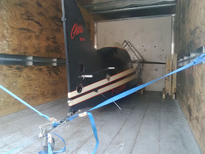
This time I rented a truck to bring the fuselage back to the hangar:


...and finally, the fuselage back in the hangar!


Next step is the paint job. Stay tuned!

Saturday 6 June 2015

Sidelugs

One of the last steps of the welding process is to weld the sidelugs on the bottom longerons. I've contacted many local sheet metal shops to see if they could bend the 0.025" thick 4130 sheet I had. The bends required are close to each other and shops were generally reluctant in doing the job. I therefore decided to make them myself.

My initial design looked like this:

 
The original sidelugs did not include the step as you can see above. I needed to add this step in order to accomodate the new thickness change of the lower longerons. However, making this out of one piece with the few tools I have was a little complex so I decided to split it into two parts:
 
 
Had to make a holding tool to make sure that the metal was securely held in place. I used two pieces of 3/8 thick mild steel with a little radius on the corner of one of them. Here is what my bending setup looked like:


I used screws going through both plates to provide additional clamping force near the edges. The bar you see on the right is a piece of 1/2" thick steel I used to hammer the base of the protruding part of the sheet metal. It took a lot of effort to bend this only with a hammer. After two nights of work, I had the four pieces bent the way I wanted:


The last step before welding to the fuse is to trim the excess material used to clamp them in place. I left this job to my welder since he is going to determine their final location and might need extra length.
 
Next post will be about the final welding and if everything goes well, about the ferry back to my home airport!