Monday 27 April 2015

Rack on tracks

My apologies for the lousy title... running out of rack jokes now. Yesterday was a big day in my repair process since my welder was coming at the airport to pick up the fuselage.

The day started with the last step of the homework he gave me before picking up the fuselage: burn off the paint on the aeras that will require welding work. My friend Scott came to the hangar with his torch to do this. It needed little heat to make the paint peel off. After the burning process, I removed the burned paint with a stainless steel brush. Will post pictures of the bare metal in a future post.

Little parenthesis: once this was done, I had a little spare time before the appointment so I decided to make the dye penetrant inspection on my header tank. It turned out a pinhole seemed to be the problem (red dot in the middle of the picture):

End of parenthesis.

Next step was the big one: secure the fuselage on a pick up truck and bring it to the welding shop. I am no pick-up truck expert, but I was expecting something a little bigger. I know it looks kinda crazy but we found a way to safely strap it on the truck:


Drove all the way down from CSE4 to CYUL and managed to mount it back on the super rack, intact in the shop. Phew! Thanks much to my welder, Mark and my friends Marc and Scott who helped me that day. And yes, I am considering a larger vehicle to bring it back in a few weeks!

I'm currently waiting for the 4130 tubing to arrive from Spruce. Plan is to make a little maintenance on my brake system in the meantime!


Wednesday 22 April 2015

Nice Rack

This evening, I used my fuse support again and sawed off the last piece of tube I needed to remove: the RH side diagonal (#1). Unlike the LH one, this member has not been repaired and was therefore much easier to remove since there was no ugly, distorted splice welded to it. I took a picture similar to the LH one so that you can see the difference...


Before my welder comes and pick up the fuse to bring it to his shop, last step is to remove the paint around the areas that will need welding. I intent to use a combination of heat and steel brush to achieve that. It's good to be slowly reaching the end of the tear down process. Not there yet, but close!

Monday 20 April 2015

Rack'n Roll

Last couple of days, I really experienced the benefits of my fuselage support. Once I removed the gear with the help of my friend Marc, I could swivel the fuse around to reach areas that would have been difficult to access without it. Wx was nice outside so I could make some progress on the tube cutting:


I tried various cutting methods and the best compromise I found between precision and efficiency was using a Dremel with 1 1/2 in diameter cutting disk for metal. I even tried a buffer tool but it is too big to perform the precision cutting when getting around a tube to be preserved and is not much faster than the Dremel.


 The following is the status of what I cut from the structure and what remains to be removed:
  1. Gear support diagonal - Done LH - RH to be removed
  2. Nut plate attachment lug - Done both LH and RH
  3. Bottom central gear support - Done
  4. Bottom gear support reinforcements - Done both LH and RH

Here's a CAD view to better visualize what parts I removed. I highlighted in blue the members in question. Note: I didn't model the nutplate attachment lug (#2):


...and here are the reasons for the removal of each member, again with the same numbering convention:

  1. The LH diagonal was terrifying and I intend to comply with the Steen S1 drawings i.e. replace them with 3/4 in 0.035 wall tubing (was 5/8 0.035). Also, removing these will help getting access to install the lower longeron reinforcement sleeves:
  2. Also need to remove the nutplate lugs to allow the installation of the longeron reinforcement. 
  3. The welds were bad and the gear bolt bushing were welded to it. Since I will not need the inboard bushings (passing from 4 bolts per side to only 2), I decided to replace this member and remove everything I don't need anymore.
  4. Same reasons as 3.

The CAD picture above also doesn't show the gear support flat plates in between which the gear was held. Here are a few pictures that progressively show the parts removed:


Before the removal of RH#4 and a part of #3:


Another view.. This one is very interesting: the crack due to the torsion of the gear is obvious. The crack propagation  is close to 45° which is a typical failure mode for round elements in torsion. ATTENTION PITTS OWNERS WITH SPRING GEARS WITHOUT RADIUS PLATES: THIS IS THE CRACK YOU DON'T WANT!!


Finally got the RH assembly removed:


Same cuts on the LH side (one of your last chances to admire the masterpiece (of shit) of an unknown welder):


Another interesting picture here.When I removed the RH nutplate support lug (#2) another crack was hidden under! This one seems also due to torsion, but aft of the spring gear. With time, the longeron section sitting on top of the gear would have probably broke, which is most likely what happened on the LH side. Makes sense doesn't it?

AGAIN SPRING GEAR PITTS OWNERS, CAREFULLY INSPECT YOUR LONGERONS HERE!!

Big thanks to my friend Scott who helped me pull the fuse back inside:


And last but not the least, a picture of some acro with Marc in the Citabria before my grinding Sunday : )


Coming up next: the removal of diagonal #1 RHS!

Wednesday 15 April 2015

Full rack

This evening I finished the rack to support the fuselage. It allows the fuselage to rotate along its axis in order to provide better access to areas underneath. I made a triangle shaped frame in order to reach three engine mount bushings and let the fourth one free of any wood structure:


Different holes can be used with the dowels allowing to lock the position at 45° steps. The triangle frame can also be flipped over to let access to the RHS if required. I set the height so that I can easily remove the gear, however the price to pay is that the vertical fin doesn't clear the ground so I will warn my welder not to turn it past 135°!

Next target: gear removal and resume the grinding!

Sunday 12 April 2015

The first cut

Last week, my friend Marc helped me removing the tail surfaces. Two surfaces were a little more complicated to remove: the RH elevator and the LH stabilizer. The RH elevator was a little puzzle due to the trim tab cable going through it. What we ended up doing is removing the cable from the sleeve. This made the sleeve much more flexible and solved the problem. The LH stab was simply stuck on its leading edge attachment. I've put some LPS 2 lubricant and let it penetrate a few minutes and finally got it off.

This is what the fuse looked like once the tail surface were all removed:


This week-end I had an appointment with my welder, Mark Clément from Aérosoudage. The objective was for him to inspect the structure and determine the work to be done. The conclusion was encouraging; all bad tubes and bad welds can be either replaced or repaired. I am going to have to bring the fuse to his shop; this will help him getting a good setup and maximizes the chances of having a high quality repair. However, before that I have some homework to do: saw off the bad tubes and burn off the paint around all areas where welding will be required.

I also had the idea to build a support for my fuselage that is going to allow it to rotate. This is in order to help my welder to have good access to the areas that need work. I asked him if my idea was going to help him and he said it was going to make a good difference so I dedided to proceed. I bought the wood, cut it and started assembling it:


Today, wx was really nice and I couldn't stand the 2D world anymore so I went for one hour of fun in the Citabria in the morning.

Once back at the hangar, I decided to continue taking advantage of the nice wx and pulled the fuse outside and start my homework. I don't want to do any metal grinding in the hangar as it creates a lot of dust. I chose to saw off the member that I hated the most first (NB: don't apply this last sentence to members of your family). The sound of my airplane being sawed-off was a tad annoying at the beginning, but I finally got used to it...


Once the tube in question was removed I could appreciate how bent it was...


I also removed the lug on which the side panel nutplates are mounted:


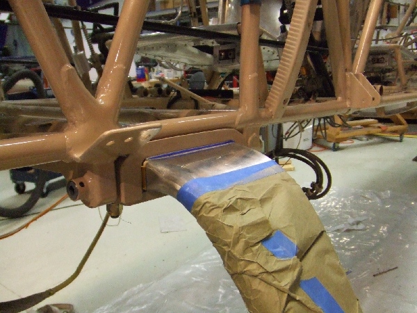
Nice view of the lovely welds on the LH side. Admire the beauty of the paint on the gear and hardware. I am so anxious to clean all this...


That's about all I could do on the fuse before I mount it on my super rack and remove the gear.

I also went to Scott's hangar today to have advice about a repair I noticed on my header tank when I removed it last week. The tank seemed to be patched with fiberglass and an epoxy based compound that was hard like rock. Since I'm going to have a welder available, I thought I was going to convert this small repair also into a proper repair. Had no idea how to remove that stuff...


Good thing Scott knew that it took only a little heat! Used a paint removal heat gun and scraped off the compound quite easily:


I did not notice any crack under it, even with a magnifier. I suspect there was a leak there so I think I'm going to perform a dye penetrant inspection to see if there is a crack or a pinhole there. If so, I'll mark it for my welder.

That's about it for this week-end! I'm happy of the progress I made in the last coupe of days. Next time I go the hangar, my objective is to finish the assembly of my fuselage rack. Stay tuned!


Friday 10 April 2015

Removals

Ok so here are tidbits on the removal process.

First thing I chose to do was to remove the engine. I found a guy on my home airport that had a hoist I could use to lift the engine. Had to buy the clamps to attach the chain on the crankcase. I decided to buy two and have two attachment points in order not having to remove all the injection system just to lift the engine. I also decided to remove the engine along with all accessories, engine mount and even the firewall all together:


The engine removal took me about two full days to do.

Then I had to build a wing rack that had to be compact and on wheels to move in around since we're two airplanes in a small hangar. The rack took me a full day to build, then with the help of a friend, I started removing the bottom wings, followed by the top wings.

The hangar being small, I realized at that point I had too many parts laying around so I decided to build some shelves and wall racks to store my parts:


Few days later... More shelves and the fuel tank removal:


Again few days later, the panel and systems removal including throttle cable, fuel system, rudder pedals and brakes:


So here I am today. I am now at the point where I need advice on the welding process (which parts can be fixed/changed, preparation, how to minimize the deformation with welding heat, etc.) I will touch base with a professional aviation welder that know well the 4130 chromoly...

What happened?

Once I got back home, I couldn't wait to get to the hangar and see if I had those radius plates. It turned out I didn't. My installation was something particular with four bolts per side to attach the gear with big, wide flat plates...

Having now more information on the problem, I made a better inspection of the fuselage structure and found the following:

  • The fuselage tubing paint around the gear area on the LH side is starting to peel off and light surface corrosion is starting. The paint on the RH side is all nice and glossy.
  • Some welds on the LH side look like shit, seriously. Maybe shit is nicer actually. The RH side equivalents are superb.
  • The cracked diagonal on the LH side has a fishmouthed sleeve which indicates it's been repaired. Also, if I looked along the tube axis, I could see it was bent.
  • The lower LH longeron seem to have a weld along its axis near the gear location, which is not present on the RH lower longeron.

In light of the above observations, here is my theory of what happened to this aircraft in the past:

  • At one point in time, the left longeron was badly damaged due to the torsional loads and the owner did not realize.
  • Then something major happened, probably the gear collapsed into the fuse on one side during landing. Hopefully the airplane was not ground-looped. The bottom wings don't look repaired and the fabric is not patched.
  • Unfortunately, the owner at that time probably didn't know about the radius plate fix, and simply welded back the pieces together, without fixing the root cause of the problem.
  • The repair was done quickly, probably without removing the engine or the systems, explaining the paint marks on the purge valve sleeve.
  • The welds being so bad, they created a stress riser in a rough area and it cracked.

Now what? What do I do with all this? One thing for sure is I want to install radius plates so I ordered some to Grove Aircraft. One other thing for sure is I want to remove and replace the cracked member. I am still not fixed today on whether or not I change other members of the forward fuse or if I just install beef-ups like a sleeves or gussets. Anyway, the removal of the cracked member involves the removal of the engine, wings, fuel and systems in order to have the best access to the damaged area and do a proper job. Next post will be on the progress of the removal of engine, wings and systems.

The research

The day after The Finding, I was flying to Wichita for business and I remember all sorts of questions were going through my mind. How am I going to fix this? How long I'm going to be grounded? But mainly: Why is my fuselage cracked?? I left home that morning with the firm intention of coming back two weeks later with answers to my questions.

Here's a little summary of what I found by talking to Pitts gurus in Wichita and on forums.

  •  There is an old, well known problem with spring gears mounted on metal tube fuselages: if the attachment points are rigid in torsion, the flexing of the spring gear induce torsional loads on the longerons which will fail with fatigue, one day or another. The Grove Aircraft company in California has a website that illustrate this well:
  • One way to prevent these torsional loads to be transferred to the fuselage structure is to install radius plates instead of flat plates in between which the gear is clamped. This allows some flexing along the X axis. As the gear flexes, the line of contact will follow the radius and therefore only forces will be transferred to the fuse, not moments.


I found the following references regarding the installation of radius plates on different aircraft:

I also learned that the Pitts Model 12 and the Steen AeroLab S1 are designed with radius plates.
  • The heavy duty installation is to create a hinge like the Extra 300. However this is something quite difficult to retrofit on an already existing fuselage:
Source: NickyP on biplaneforum.com

  • With a spring gear installation, the fuselage needs additional strength compared to the original bungee gear fuselage. The diagonal member that go from the back of the gear to the top engine mount attachment point is not part of the original Pitts plans and is specific to the spring gear installation. In addition to that, Steen adds a sleeve over the forward portion of the bottom longeron to provide additional strength at the gear location. See Biplane Forum threads here and here.
  • A spring gear on a Pitts typically requires the installation of a "butterfly plate" i.e. an aluminium sheet that is bolted to the center of the gear as well as on the gear attachment points. This plate is to prevent lateral movements of the gear (along the Y axis) relative to the fuselage. See biplane forum thread here.
Now, what do I have on my airplane? The diagonal member is there; it's the one cracked! For the radius plates, I did not know until I came back from my trip. But even if I didn't, how come the crack appeared near the top longeron? I had to come back home to answer these questions...


The finding

I anticipate many posts on this topic since it's going to take quite some time for me to fix.
 
Recently I was working on a little upgrade of my fuel system. This involved removing a panel I never removed before, under which I noticed a crack on the fuselage structure. Sheesh. I immediately called my Pitts mechanics mentor and he confirmed what I feared: having to tear the airplane down. DoubleSheesh.

Here are progressively frightening pictures (not for the faint-hearted aviation geeks like me)


I made this lovely finding one day before leaving for a 2 week business trip, not really knowing what to do. I took this opportunity to make some research on my spare time abroad. Next post will be on the results of this research and on the different advices I got from many people I contacted during this trip. One thing to notice on the last picture is the grey paint mark on the purge valve cable sleeve. I'll explain my theory on why this happen also in future posts...

Background info

Hello reader,

Here's a little background info on my story with my Pitts. I am a fairly inexperienced Pitts owner/pilot. This is only my personal experience and I do not pretend any of the content of this blog to be applicable to all Pitts owners/pilots. Everybody have different experiences and different approaches in owning, maintaining and flying an airplane. I share part of my experience here because I received a lot of help from members of the aerobatic/biplane community and felt I had to share my humble experience of owning a Pitts.

I bought my airplane in 2013. I've been lurking single seat Pitts for 2 years and actively searching one for 3 months before I bought mine. Heard all sorts of stories about how hard it is to land and some almost discouraged me of buying one. When I bought it, I already had a share on a Citabria with about 150h of tailwheel time, but still, I was a little scared of those stories. With my Citabria time and an intensive training on an S2B completed, I finally got to fly my Pitts for the first time. My dream came true.

It is a different airplane for sure and I can hardly imagine anybody flying one without proper training. I did not find it unpredictable or unstable. It's just very different from any other airplane I flown, mainly for its lack of forward visibility and its surprisingly nervous flight controls. It is some work, but extremely rewarding. There's nothing like it. Flying a single seat, 17ft wingspan biplane is an experience I can hardly describe.

My Pitts was built by Jim Killough in the late 70s. I heard from the last owner that it is apparently his 7th Pitts built! I cannot confirm this information but so far I am aware of three other S1's built by him before mine and the dates seem to match up. It has been fitted with a 200 hp angle valve IO360 engine since day one according to the logs. With the impressive amount of incidence on the vertical fin, I think Jim had this engine in mind early in the building process. The airplane had a major rebuild in 2002 and the top wing was rebuilt and recovered by Joe Flood in 2008. Here are other items my airplane was equipped with when I bought it:

  • Plywood leading edge and 4.2 gallon aux tank in the top wing
  • Spring gear
  • Header tank
  • Airflow Performance FM-200 injection system with purge valve option
  • B&C starter, alternator and spin-on oil filter
  • Cross-over exhaust
  • Christen inverted oil
Here's a picture from an air-to-air photoshoot I organized with friends a few months after I bought it:


I hope you will enjoy reading my posts! They are intended to be rather technical; this post being probably the least. Feel free to provide comments or questions on any of them!