Tuesday 1 February 2022

New Spinner - 2 of 2

Once I got the rough spinner from Catto, next task was to make the prop cutouts and screw holes. One of the reasons of my spinner replacement was improper tracking so I really wanted to emphasize on a precise tracking for this new one.

I found this interesting article on the EAA website on spinners. It explains how to make a blade cut-out template. I did try a few ways of making a template by using cardboard or scrap aluminum but I found it difficult to make an accurate and easy to use template on top of this double-curved surface.

The old spinner had the same diameter and length as the new one. The shape looked very similar so I tried using a piece of the old fiberglass spinner to make a blade cut-out template. I used a dremel with a thin cutting disk for all the rough cutting, including in the carbon fiber for the cutouts described later on. 


When putting the piece on top of the new spinner surface, it did match the shape pretty well. I therefore decided to use it as my template material. I used my cardboard template attempt to trace the rough lines on the fiberglass template:


The curved line above shows the actual shape of the back end surface of the prop. It became clear that cutting this shape would make the spinner impossible to install, so I thought a line parallel to the forward cut was a good compromise.

Then a rather long iterative process began. With the new spinner aft bulkhead, prop and old spinner forward bulkhead installed on the engine, I made gradual adjustments to the template until reaching a cut-out with a 1/8 inch prop clearance. I could firmly hold the template against the bulkheads using side grip clamps and Cleco pins. I used a Sharpie pen to mark the areas where material removal was needed.  Then to remove material I used a curved file and most importantly, patience.

After 2 hours of back-and-forth, I finally ended up with a template I was happy with. The picture below shows the template on top of the new spinner:


I used the template to mark both cutouts on the new spinner using a fine point pen. Then I carefully cut offset cutouts with the Dremel and then refined the cutout to match the lines using a file. When trying to fit the new spinner in place, I realized the centering dowel was preventing the spinner to fully get in its position. I initially thought it was just long enough to fit in the prop crushplate. It was in fact longer than that and designed to get also into the prop hub. My Prince prop having only a 1 inch diameter center hole vs the 2.25 inch dowel diameter, I had to find an alternative. After a confirmation call with the friendly staff at Catto, I decided to shorten the dowel to ensure the spinner could slide all the way aft until reaching the bulkhead, while still performing its self-centering in the crushplate:


This allowed me to get a final fit on the airplane. I did have to make very small adjustments to the cutouts, probably due to the effect of the template thickness, but nothing compared to the making of the template itself.

For tracking, I simply used a piece of MDF wood clamped on a trestle as a ground reference. As recommended in the EAA article, I removed one spark plug per cylinder to freely rotate the prop. The centering dowel made the tracking exercise fairly easy. Only had to make small adjustments to find the symmetrical position and mark crew holes:


I was then ready for clear coat! I could have painted it black like the old spinner, but I thought a clear coat on carbon fiber was going to make a good match with the CF weaves on the Prince prop.

Since I hate painting, I sent the spinner to a good paint shop. Really anxious to get it back!

Stay tuned for the final look and final weight numbers.

Wednesday 19 January 2022

New Spinner - 1 of 2

During an acro practice session last summer, a friend of mine was looking at my airplane while I was starting the engine and pointed out that my spinner was wobbling. The wobbling motion appeared to be due to an improper tracking. This was a very valuable observation since I never got to see my spinner turning myself.

I was sometimes missing a spinner screw after a flight, despite using loctite and locking nutplates. Vibrations due to this improper tracking were probably the main root cause. These were signs that the spinner was due for a change. Loosing a spinner in flight can really become a catastrophic scenario. So I began making some research. As I am looking to shift the CG back on this airplane since it is nose-heavy, I was also looking at the opportunity to save weight.

No matter what spinner I chose, I was going to need a dynamic re-balancing. I therefore decided to buy the Skydynamics featherweight flywheel and change my flywheel at the same time. 

Next was the spinner itself. My old spinner was made of fiberglass with two aluminum bulikheads. I can't say for sure what type it is, but it appears to be the Vans 13-inch spinner. 

First thing I did was to remove spinner and prop to get the actual weight of my spinner assembly. Turned out to be 3lb 8.6 oz including bulkheads and hardware.

I contacted Rob Millinship at aerographic in UK since I knew they were making nice CF spinners. Rob said they focused on sturdiness and that their spinner weighed probably more than a standard aluminum spinner...

I didn't find tons of info on the web on other spinner weights. Here are a few from Aircraft Spruce:


SN4 spinner kit (most likely discontinued):


BN-3 spinner kit (also most likely discontinued):


Catto spinners:


Vans spinner: no weight information on their website, but according to friends on the Biplane Forum, the new assembly weighs about 2lb 14 oz + hardware, so about 3 lb total. 

Also looked at other types, but couldn't find weight info on them or were not adapted to my installation.

Catto was more expensive, but appeared to be the lightest option. What I also found interesting is their fwd bulkhead design: it is glued and has a self-centering dowel helping for proper tracking:


The dowel is designed to fit into the crushplate center hole. It has a 2.25 inch dia and appears to be slightly tapered to ensure a snug fit.

For the above reasons, I opted for the Catto spinner and got great service from the team at Catto.

Once I received the spinner assembly from Catto, I couldn't resist to weigh it to compare with my old spinner. In summary:

  • Old 13 inch spinner: 3lb 8.6 oz
  • New catto 13 inch spinner: 2lb 4.0 oz (rough i.e. no clear coat and no prop cutouts)
  • Old lycoming flywheel (with grinded alternator pulley): 5lb 6.8 oz
  • New Skydynamics featherweight: 3lb 2.7oz

...overall these changes may take more than 3.5 lb off the nose! Weight saving there is like killing 3 birds with 1 stone: less loads on the crankshaft during tumbling maneuvers, less forward CG clipping and less weight!

This is promising...

Next post will be about the prop cutouts and tracking (hopefully better than the old spinner!)


Tuesday 18 January 2022

Recap on Engine Installation

When I left this blog few years ago, I didn't take the time to write on my engine installation after the Titanium firewall was complete! Before getting into other topics, I will just wrap up this chapter first.

It went fairly smoothly since there was no change to the accessories and hoses. Again, I found easier to mount all of them as well as the engine mount while the engine was still on the hoist. Then I could precisely position the FWF assembly against the firewall with the help of my dad and the engine leveler:


While the engine was gone in the shop for repair, I also took the opportunity to modify by exhaust to provide more support. When I bought the airplane, the whole stack was held only by the cylinders, and each time I was pulling Gs, I had this fear of having a cracked exhaust after my flight.

I looked at several attachments on other aircraft, including some fancy ones linked to the engine mount with springs to allow movement... It seemed overly complicated to me since I did have attachment points available directly on the engine oil sump. This didn't require springs since the exhaust is moving with the engine.

I spent quite some time looking at the engine to find the easiest way to hook the exhaust. Took some cardboard to simulate small brackets. I ended up with two brackets, one for each pair of my crossover exhaust. 

I gave precise instructions to my welder in order to add two lugs to the exhaust with my desired angles. I then took the exhaust for ceramic coating since I got rid of the fiberglass wrapping and wanted to mitigate the risk of high cowl temps. Once I got everything back in the hangar, I was pleased with the fit of the exhaust with my new SS brackets:


Another fix that helps quite a bit my peace of mind!

One other thing that was long overdue was the making of new baffles. The old ones were patched, cracked and the baffle seal was all dried up.

Never underestimate the amount of time required to make new baffles from scracth... Took me in average a day for each baffle panel. Used all sorts of tools like an air nibbler to make the first rough cut and then a beverly shear for the finish cut. My friend Scott's tools were again very useful!


I used the old baffles as a template basis, with cardboard at some locations where I wanted an extension of the metal to better follow the cowl's inner shape. Lots of trial and errors, but perseverance paid off and I was quite happy with the end result:


Last step was to install the silicone baffling material (that's the fun part). I decided to use #4 screws with heat nuts instead of pop rivets to better control the pressure on the silicone material. This helped minimizing the ripple effect when excessively squeezed.


Once the baffles were finished, I painted them to protect them against corrosion, Reinstalled all panels and cowling, made a good wash to the airplane, weighed it and then went flying!

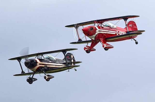
It felt so good to get back in the air again. Here's a few shots taken by Stephen J. Thorne (awesome photographer) in Gatineau (CYND). Formation was with my friend Peter Ashwood in his beautiful S-1T:


...Now back to 2022 winter! With my house almost done, I can finally get back in airplane mode and I have the following plans for this winter:

- New Spinner 
- New Lexan belly
- Battery relocation 
- ELT 406 installation
- AV30 + TailbeaconX installation

That's quite a bit for this winter but hopefully I can get all of this done in time for the spring weather!

Thanks for reading!


Sunday 19 September 2021

News

I know I know I know, it's been years of inactivity on this blog. Apologies to my old followers; lots of changes in life made my free time very rare, but I'm seeing  the light at the end of the tunnel and it's not a train.

Main reason of my absence is the self-construction of a new hangar-house in the Lachute airpark (CSE4). Been working full time at the same time... Boy, what a committment. But after a year of preparation and 2 years of construction, it is soon coming to an end.

The Pitts has not flown much during that time, and I missed it a lot. Construction has been consuming pretty much all of my hobbies. Next year will be the big come-back to my normal life where the hammer will leave its place back to books, music, sports, a social life and the Pitts control stick.

Have a few projects for the Pitts coming up so I will have interesting updates from time to time!

Here is the Pitts in its new house : )


Saturday 28 April 2018

Titanium Firewall Part II

Once I finally got the engine back, I decided to make a firewall template out of coroplast before drilling my new titanium firewall (thanks to my friend Mathieu Gratton for the idea!).


This allowed me to try different hole locations and converge on routings for hoses, controls and wires that I was happy with. Took a lot of notes directly on the template for me to remember all details as I was trying each setup. 


I used the green tape on the coroplast to mark the location of the structural members of the fuselage. This helped to avoid holes or nutplates at a wrong location!

For the most critical elements like throttle and mixture cable holes, I placed the engine  as close as possible to its final location (the engine leveler helped a lot for that):


After taking some time to look at all this I decided to relocate the starter solenoid as well as the voltage regulator which were both mounted on the firewall before. The battery being behind the seat, it makes more sense to have the unprotected cable between the battery and starter solenoid as short as possible (I don't have a master solenoid). Also, after looking at specs from B&C aero, it is generally recommended to locate the voltage regulator behind the firewall for cooling reasons.

Once I figured out where I wanted all holes to be drilled, I transferred the final markings to the titanium firewall and drilled all I could using the press drill. Obviously some holes were too far from the edge so had to use a hand drill for these. Most of the holes were easy to drill with cobalt bits. The larger diameter holes were more of a challenge. Biggest hole was 1.0 inch. I used a unibit but it required patience since titanium is quite hard. Clamping the Ti sheet to a thick piece of wood helped. I also used cutting oil between each step and reduced the drill rpm as the hole was gradually getting bigger. Slowly but surely, I finally got there.

Last step was to install the nutplates. I also decided to rivet reinforcing brackets at two locations where more stiffness was required: behind the 802 oil valve and behind the brake fluid reservoir. I used a C-frame to make dimples and riveting (thanks to my friend Scott!)

As a comparison, here is the old SS firewall a.k.a. swiss cheese firewall:


Here's the wannabe firewall:


...and the final result:


Much less of a swiss cheese now : ) Next step is the engine installation!

Monday 16 April 2018

Titanium Firewall Part I

While the engine was gone last year, I decided to take the opportunity to make a new firewall since the old one had many unused holes that were plugged. In fact it looked more like a slice of swiss cheese rather than a firewall.

The old material was a 0.025" thick sheet of stainless steel. When browsing on the biplane forum, I saw that some builders were using titanium to save weight! Since my airplane is a little nose heavy, switching to Titanium was killing two birds with one stone.

In order to select the material thickness, some guidance exists under FAA 14 CFR 23.1191 which says:

(h) The following materials may be used in firewalls or shrouds without being tested as required by this section:

[...]

(6) Titanium sheet, 0.016 inch thick.

I therefore proceeded an ordered a sheet of 0.016" thick titanium from Titanium Joe. Great service and quick shipping. First impression: ok Titanium is VERY light.

I used the shape of the old firewall to draw and cut the titanium sheet to the desired shape. I cut the biggest parts on a heavy duty straight shear and cut to final shape with curves using a shear similar to this:

Image result for metal shear

Then I drilled the holes for the aluminum frame rivets them using a cobalt drill bit and the old firewall:


When looking at my neighbour Luc with his Pitts S-2C, I realized the lower edge of his firewall was actually bent with a large radius in order to reduce air restriction and make it easier for the warm air to get out of out of the cowl. My old setup had a sharp edge corner which obviously created a lot of turbulence and air restriction. I didn't especially had oil temperature or cylinder temperature problems, but since I may relocate my oil cooler eventually, I thought I was putting all chances on my side to make a large radius bend like on the S-2C. Easier to block air down the road rather than to unrestrict it!

In order to block the gap between the radius and the flat adjacent areas, I had to make small brackets using the leftover titanium:


Here is the result after the aluminium frame was transferred to the titanium firewall and the work on the bottom edge complete:


Next step was to locate and drill the required holes. I didn't want to blindly copy/paste the old hole locations so I prefered to wait until the engine was back before proceeding... To be continued!

Tuesday 26 December 2017

News from the engine shop

It's been a long time since I wanted to write this update and the Christmas holidays is perfect for it : )

The main symptom my engine had was typical: corroded lifters and cam lobes. Two lifters were definitely not airworthy:


The source of the metal found in the filter was mainly from the lifters. When reading this article about lifter destruction stages, it is pretty evident that these were in stage #3 and had to be replaced.

Since the cam was not in good shape neither, it also had to be changed. Took the opportunity to switch to a high performance cam (different lobe shapes that modify the lift and duration to optimize valve timing and increases combustion efficiency)

This engine only has 500h since new. The cylinders were inspected at the shop and were found in good condition so it was worth taking this opportunity to proceed with porting/polishing of their induction and exhaust tracts as well as carry out a flow balancing on them. This allows a higher volume, to flow with greater efficiency to and from the combustion chamber, hence producing more power.

While the cylinders were getting ported, the crankcase and oil sump got completely cleaned and painted:


The reassembly was also initiated:


Once the cylinders were back, they went for honing, but this revealed an unpleasant surprise: the inside of the cylinder walls were also affected by corrosion:


The solution for this was to oversize the cylinders by 0.010". This howevers means new, oversized pistons and rings. Here's a shot with the cylinders painted and the new pistons followed by pictures of the final assembly:


Once the final assembly was done, the engine got installed on a test bench with a dyno. They ran it for a few hours and checked twice the oil filter for metal. Thank God nothing was found this time! Testing on site is is nice because the break-in of the engine is actually done at the shop. Dyno results were also interesting: with the high performance cam and ported cylinders, the engine produces about 10% more power at 2700 rpm.

The engine is still in the shop of Aerorecip in Winnipeg; it will be shipped right after the new year! Been working on a new firewall in the meantime which is going to be the topic of my next post.

Happy holidays to all of you my readers! I hope 2018 will be full of happiness and interesting projects for you!