Showing posts with label landing gear. Show all posts

Sunday, 20 March 2016

Landing Gear Installation

Today, a great milstone was achieved on my rebuild: I reinstalled the landing gear with its new attachment points design.

As explained in this post, a major change in the way the gear is attached to the fuse was required. I got the last part I needed last week: the butterfly plate. Big thanks to my friend Scott for cutting the part with his router. I also thank my brother-in-law Jean, who anodised the part in his shop!

So here's the assembly.

Orange: butterfly plate made of 0.065" thick 2024-T3 aluminium (grey anodised)
Green: radius plates made of 7075-T6 aluminium (black anodised)
Blue: Backing plates made of 303 SS


I lifted the tail high enough so that the bottom longerons are parallel to the ground, easing up the installation of the gear:


Once all fasteners properly torqued:


Details of the stack:

Next step is to prep the engine before reinstalling on the airframe. I like where this is going  : )


Tuesday, 19 May 2015

First pieces tack welded

Quick update to mention that the lower longerons were tack welded in place yesterday! The forward gear bolt bushing alignment was also checked to ensure that the gear was going to be at the desired location:


Square channels were used as a guide to check the gear alignment:


Mark is also going to weld a reinforcement plate for my wobble pump attachment bracket that was cracked. I took the opportunity to drill nutplate holes to ease up the installation:


Next step is the final welding of the lower longeron reinforcement sleeves. Stay tuned!

Tuesday, 5 May 2015

Last steps of dismantling

Over the last week, Mark made great progress in removing the excess welding maetrial from the old repair. He pretty much removed everything that needed to be removed except the portion of the flat plates still welded to the bottom longerons.
 
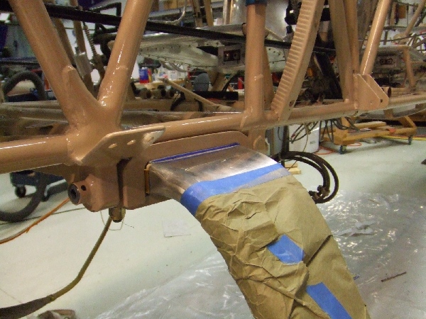
I wanted to use these plates one last time before removing them and here is why. As I need to oversize the gear attachment bolts (AN5 to AN6 size), I need to get rid of the old bushings and replace them with larger ones. I decided to progressively drill them out until reaching the OD of the new bushings. In order to achieve that with reasonable precision, we decided to fix a mag drill on a steel beam sitting on the bottom longerons while the fuse was mounted upside down:


As you can see, having the old flat plates still welded to the longerons was a good reference to clamp the steel beam on the fuse. Big thanks to friendly Claude from whom I could borrow the mag drill.
 
While Mark was working on removing the old welding last week, I decided to take the opportunity to make a small modification to my landing gear. I wanted to do this for a long time and since everything is teared down, it is much easier to do it now: rotate my brake calipers aft. My original setup was with the calipers mounted downwards and I didn't like much the idea of scraping the caliper on the ground if I ever have a flat tire or tire burst.


After a few tests playing with the different components, I found the caliper position that I think was a good compromise; it needed a small adjustment of the nutplate attachment lug and a bit of trimming on my wheelpants.

First I washed the wheel hub and brake parts with varsol to have clean parts to work with:


Then, I slightly trimmed the nutplate lug, and with the use of a cardboard template and my Dremel with a cutting wheel, I trimmed of the piece needed on the wheelpant:


And here is the almost-final result:


I'm going to have a little extra trimming to do to clear the fitting on the top, but I preferred to have the final fitting in hand before doing that.

The 4130 steel tubes and plates are in transit right now. With chance, I will receive it this week and start trimming the first tubes this week-end!

Friday, 10 April 2015

What happened?

Once I got back home, I couldn't wait to get to the hangar and see if I had those radius plates. It turned out I didn't. My installation was something particular with four bolts per side to attach the gear with big, wide flat plates...

Having now more information on the problem, I made a better inspection of the fuselage structure and found the following:

  • The fuselage tubing paint around the gear area on the LH side is starting to peel off and light surface corrosion is starting. The paint on the RH side is all nice and glossy.
  • Some welds on the LH side look like shit, seriously. Maybe shit is nicer actually. The RH side equivalents are superb.
  • The cracked diagonal on the LH side has a fishmouthed sleeve which indicates it's been repaired. Also, if I looked along the tube axis, I could see it was bent.
  • The lower LH longeron seem to have a weld along its axis near the gear location, which is not present on the RH lower longeron.

In light of the above observations, here is my theory of what happened to this aircraft in the past:

  • At one point in time, the left longeron was badly damaged due to the torsional loads and the owner did not realize.
  • Then something major happened, probably the gear collapsed into the fuse on one side during landing. Hopefully the airplane was not ground-looped. The bottom wings don't look repaired and the fabric is not patched.
  • Unfortunately, the owner at that time probably didn't know about the radius plate fix, and simply welded back the pieces together, without fixing the root cause of the problem.
  • The repair was done quickly, probably without removing the engine or the systems, explaining the paint marks on the purge valve sleeve.
  • The welds being so bad, they created a stress riser in a rough area and it cracked.

Now what? What do I do with all this? One thing for sure is I want to install radius plates so I ordered some to Grove Aircraft. One other thing for sure is I want to remove and replace the cracked member. I am still not fixed today on whether or not I change other members of the forward fuse or if I just install beef-ups like a sleeves or gussets. Anyway, the removal of the cracked member involves the removal of the engine, wings, fuel and systems in order to have the best access to the damaged area and do a proper job. Next post will be on the progress of the removal of engine, wings and systems.

The research

The day after The Finding, I was flying to Wichita for business and I remember all sorts of questions were going through my mind. How am I going to fix this? How long I'm going to be grounded? But mainly: Why is my fuselage cracked?? I left home that morning with the firm intention of coming back two weeks later with answers to my questions.

Here's a little summary of what I found by talking to Pitts gurus in Wichita and on forums.

  •  There is an old, well known problem with spring gears mounted on metal tube fuselages: if the attachment points are rigid in torsion, the flexing of the spring gear induce torsional loads on the longerons which will fail with fatigue, one day or another. The Grove Aircraft company in California has a website that illustrate this well:
  • One way to prevent these torsional loads to be transferred to the fuselage structure is to install radius plates instead of flat plates in between which the gear is clamped. This allows some flexing along the X axis. As the gear flexes, the line of contact will follow the radius and therefore only forces will be transferred to the fuse, not moments.


I found the following references regarding the installation of radius plates on different aircraft:

I also learned that the Pitts Model 12 and the Steen AeroLab S1 are designed with radius plates.
  • The heavy duty installation is to create a hinge like the Extra 300. However this is something quite difficult to retrofit on an already existing fuselage:
Source: NickyP on biplaneforum.com

  • With a spring gear installation, the fuselage needs additional strength compared to the original bungee gear fuselage. The diagonal member that go from the back of the gear to the top engine mount attachment point is not part of the original Pitts plans and is specific to the spring gear installation. In addition to that, Steen adds a sleeve over the forward portion of the bottom longeron to provide additional strength at the gear location. See Biplane Forum threads here and here.
  • A spring gear on a Pitts typically requires the installation of a "butterfly plate" i.e. an aluminium sheet that is bolted to the center of the gear as well as on the gear attachment points. This plate is to prevent lateral movements of the gear (along the Y axis) relative to the fuselage. See biplane forum thread here.
Now, what do I have on my airplane? The diagonal member is there; it's the one cracked! For the radius plates, I did not know until I came back from my trip. But even if I didn't, how come the crack appeared near the top longeron? I had to come back home to answer these questions...